
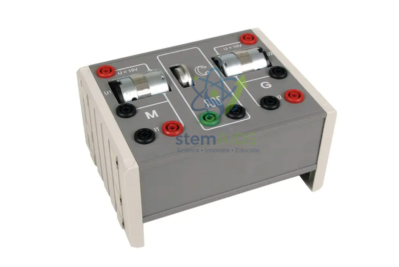
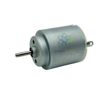
Quick Answer: This motor and generator model is a demonstration machine that works as an electric motor when current is supplied and as a generator when its shaft is turned, showing that the two are the same device run in opposite directions of energy transfer. Teachers use the motor and generator model to teach the motor effect, electromagnetic induction and energy conversion.
One Machine, Two Directions
Inside every simple motor or generator is a coil that can rotate in a magnetic field. Supply a current and the motor effect produces forces on the sides of the coil that turn it: electrical energy becomes kinetic energy. Turn the coil by hand or with a falling weight and its sides cut through the field, so an emf is induced and current can flow in an external circuit: kinetic energy becomes electrical energy. A model built to do both lets students see the symmetry without changing equipment.
Two rules of thumb sum up the directions. Fleming’s left-hand rule gives the direction of the force in a motor from the field and current; the right-hand rule gives the direction of the induced current in a generator from the field and motion. Using both on the same model helps stop students mixing them up. How the coil connects to the terminals, through a commutator for direct current, slip rings for alternating current or both, should be confirmed before ordering, since it decides whether the generator output is DC or AC.
Demonstrations
Run the model as a motor from a low-voltage supply and show that reversing the connections reverses the rotation. Then disconnect the supply, connect a sensitive meter or a small lamp and turn the shaft: the meter deflects, more strongly the faster it is turned. Turning with a lamp connected feels harder than turning with the terminals open, because the current in the coil produces a force that opposes the motion, Lenz’s law made tangible. Coupling the shaft to a second machine, such as a 12V DC motor, lets one drive the other, a direct demonstration of energy passing from electrical to kinetic and back.
Applications
- Showing the motor effect and reversing the direction of rotation
- Generating a current by turning the shaft and relating output to speed
- Demonstrating Lenz’s law through the extra effort needed under load
- Teaching Fleming’s left-hand and right-hand rules on one machine
Specifications
| Type | Motor and generator demonstration model |
| Principle | Motor effect and electromagnetic induction |
| Modes | Motor (electrical to kinetic) and generator (kinetic to electrical) |
| Use | Electromagnetism and energy-transfer lessons |
| Coil connection, supply rating and drive | Confirm at enquiry |
Care & Handling
- Run the motor and generator model from a low-voltage supply within its rating, and keep fingers and loose clothing clear of moving parts.
- Turn the shaft smoothly rather than spinning it violently by hand; steady turning gives steadier readings and spares the bearings.
- Keep brushes and contacts clean and dry, and do not oil the electrical contacts.
- Disconnect the supply before switching from motor to generator use.
Why Choose LabEquip
Physics teachers choose a combined model when they want one piece of apparatus to carry a whole electromagnetism sequence. It belongs to our physics lab equipment range, alongside the hand-turned dynamo model with magnet; ask through the contact page about the supply and coil connections.
Frequently Asked Questions
How can the same machine be both a motor and a generator?
Both rely on a coil in a magnetic field. Supplying current makes the coil turn by the motor effect; turning the coil makes it cut the field and induces an emf by electromagnetic induction. The machine is the same, and only the direction of energy transfer changes.
Why is it harder to turn the shaft when a lamp is connected?
With a lamp connected, current flows in the coil, and a current-carrying coil in a magnetic field experiences a force. By Lenz’s law that force opposes the motion causing it, so extra work is needed, and that work becomes the electrical energy lighting the lamp.
Does the model produce AC or DC as a generator?
That depends on how the coil connects to the terminals. A split-ring commutator gives pulsating direct current, while slip rings give alternating current. Which arrangement this model uses should be confirmed at enquiry.
How do I remember Fleming’s left-hand and right-hand rules?
Both use the thumb for motion, the first finger for field and the second finger for current. The left hand is for motors, where current causes motion; the right hand is for generators, where motion causes current.
What affects how much voltage it generates?
Four things: how fast the coil turns, how strong the magnets are, how many turns of wire the coil has and how large its area is. On a demonstration model speed is the factor students can change, and turning faster gives a larger output.
What supply should be used to run it as a motor?
A low-voltage DC supply within the model’s rating. Starting low and raising the voltage slowly shows how speed rises with voltage and avoids overloading the coil.
Last Updated: October 2026




Reviews
There are no reviews yet.