
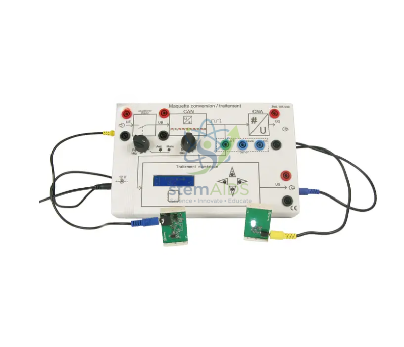
Quick Answer: The conversion and processing model is a teaching board that sets out the middle stages of an electronic system: signals from small plug-in sensor boards are converted into a form a processing circuit can use, processed, and shown on a small display. It helps students see where conversion ends and processing begins inside a real device.
Where Conversion and Processing Sit in a System
Most electronic devices can be described as a chain: a sensor acquires information, the signal is converted, a processor works on it, and an output communicates the result. The conversion and processing model concentrates on the middle two links, which are the hardest to see in a finished product because they happen on a circuit board inside a case.
Conversion usually means turning a sensor’s analogue voltage into a digital value, by sampling it and assigning it to one of a fixed number of levels. Processing then does something with that value: scales it into proper units, compares it with a threshold, or decides whether an output should switch on.
Reading the Board
The product photograph shows a white panel divided into labelled blocks, with terminal sockets between them, a small character display, a set of push-buttons and two small sensor boards connected by leads. Measuring the voltage at the sockets between blocks lets students follow one quantity through the chain and compare the sensor voltage with the number the display shows.
Because each stage is separate and accessible, the board also suits fault-finding exercises, where students locate which stage is not passing on a sensible signal.
Applications
- Tracing a sensor signal through conversion and processing to the display
- Measuring voltages at stage boundaries and relating them to displayed values
- Introducing sampling and resolution in analogue-to-digital conversion
- Fault-finding practice on a system with accessible stages
Specifications
| Product | Conversion and processing model: teaching board for an electronic signal chain |
| Features in photograph | Labelled stage blocks, test sockets, small display, push-buttons |
| Inputs | Small sensor boards connected by leads |
| Topic | Analogue-to-digital conversion and signal processing |
| Use | Bench work in physics, electronics and engineering science |
Care & Handling
- Connect and disconnect sensor boards with the supply off
- Hold sensor boards by their edges to avoid touching the components
- Keep the display window clean with a dry soft cloth
- Use only the supply specified for the board
Why Choose LabEquip
Schools and technical colleges teaching systems electronics buy a conversion and processing model to make the invisible middle of a device visible. LabEquip supplies it with output boards such as the sound and light module as part of its physics equipment; sensor options can be discussed through the contact page.
Frequently Asked Questions
What does conversion mean on this model?
In an electronic system, conversion usually means turning a sensor’s continuous analogue voltage into a digital number the processor can work with. It can also refer to adapting a supply voltage to what each circuit needs.
Why does a sensor signal need converting before processing?
Digital processors only handle numbers. A sensor produces a voltage that can take any value, so it must be sampled and represented by one of a fixed set of levels before calculations or decisions can be made.
What is resolution in analogue-to-digital conversion?
Resolution is the smallest voltage change the converter can tell apart. A converter with more bits divides its input range into more levels, so it records smaller changes.
What can students measure on the board?
They can measure voltages at the sockets between stages with a voltmeter or oscilloscope and compare them with the value on the display, which shows how each stage transforms the signal.
Which sensors can be connected?
The photograph shows two small sensor boards attached with leads. The sensor types supplied with the model can be confirmed when you enquire, together with any additional sensors the board accepts.
How does the model connect to an output stage?
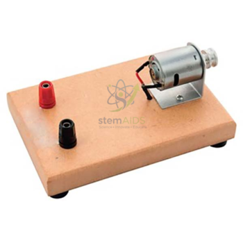
The processed result can be used to switch an output such as a buzzer, lamp or motor. Pairing the board with an output module completes the input, process and output chain for students.
Last Updated: October 2026




Reviews
There are no reviews yet.