
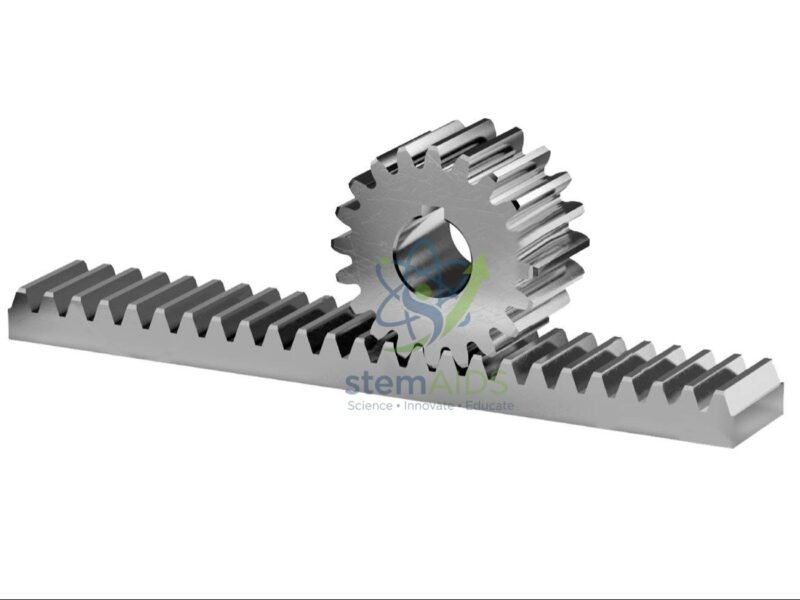
Quick Answer: Gears and Racks are toothed mechanical parts for showing how motion and force are passed from one part of a machine to another: meshing gear wheels change speed, turning force and direction, and a rack with a pinion turns rotation into straight-line motion. Gears and racks are used in physics, technology and engineering classes on simple machines.
Gear Ratio, Speed and Turning Force
When two gear wheels mesh, their teeth pass the meshing point at the same rate, so the wheel with more teeth turns more slowly. The ratio of the tooth counts is the velocity ratio: a driver with 10 teeth turning a driven wheel with 30 teeth makes the driven wheel go round once for every three turns of the driver. In exchange, the slower wheel delivers a larger turning effect, because, friction aside, the work put in equals the work taken out.
Meshing wheels always turn in opposite directions. Placing a third gear, an idler, between them makes the input and output turn the same way without changing the overall ratio. Compound trains, with two wheels fixed on one shaft, multiply ratios together and explain how clocks and gearboxes achieve large reductions.
Rack and Pinion
A rack is a straight bar with teeth along one edge; the small gear meshing with it is the pinion. Turning the pinion moves the rack in a straight line, and pushing the rack turns the pinion. In one turn the rack moves a distance equal to the number of pinion teeth multiplied by the tooth spacing. The same mechanism moves the focusing tube of a microscope, steers many cars and drives some sliding gates.
Investigations With Gears and Racks
Students mark a tooth on each wheel, count turns of driver and driven wheels and compare the result with the tooth ratio. Hanging a load from a drum or pulley on the output shaft and measuring the effort with a spring balance gives the mechanical advantage; dividing it by the velocity ratio gives the efficiency of the arrangement. The number of gears, their tooth counts, the material and the way they mount for this set can be confirmed at enquiry.
Applications
- Verifying gear ratios by counting turns of driver and driven wheels
- Showing how an idler gear changes direction without changing the ratio
- Converting rotary motion to linear motion with a rack and pinion
- Measuring mechanical advantage and efficiency of a gear train with loads and a spring balance
Specifications
| Type | Toothed gears and racks for mechanics demonstrations |
| Demonstrates | Gear ratio, change of direction, idler gears and rack-and-pinion motion |
| Typical activities | Counting turns, measuring effort and load, building gear trains |
| Used with | Spring balances, masses and a base board or stand |
| Gear count, tooth numbers, material and mounting | Confirm at enquiry |
Care & Handling
- Keep fingers clear of meshing teeth while the gears and racks are turning.
- Never force gears that bind; check alignment and remove grit from the teeth instead.
- Keep plastic gears away from heat sources and solvents that can warp or crack them.
- Store the parts in a labelled tray so small gears and pins are not lost.
Why Choose LabEquip
Physics and design-technology departments buy gear and rack sets so students can measure, not just watch, how machines trade speed for force. LabEquip lists them with its mechanics lab equipment; the wheel and axle on stand and the mechanical pulley working model cover the other simple machines. Send your syllabus needs through the contact page.
Frequently Asked Questions
How do you work out a gear ratio?
Divide the number of teeth on the driven gear by the number on the driver. A ratio of three means the driven gear turns once for every three turns of the driver and, ignoring friction, delivers three times the turning effect.
Why does the driven gear turn the opposite way?
Where two gears mesh, the teeth on each move in the same direction at the contact point, which means the two wheels rotate in opposite senses about their own centres.
What does an idler gear do?
An idler placed between two gears makes the output turn in the same direction as the input. Its own tooth count cancels out, so the overall ratio depends only on the first and last gears.
How far does a rack move for one turn of the pinion?
By the number of teeth on the pinion multiplied by the spacing between teeth, which equals the circumference of the pinion measured at the point where the teeth mesh.
Why is the mechanical advantage less than the velocity ratio?
Friction between teeth and in the bearings, and the effort needed to move the parts themselves, waste some of the input work. The mechanical advantage is therefore lower than the ideal value set by the tooth ratio.
Where are rack and pinion drives found in a laboratory?
Microscope focusing mechanisms, some optical bench carriages and adjustable stands use a rack and pinion, because a small turn of a knob gives a smooth, controlled straight movement.
Last Updated: October 2026






Reviews
There are no reviews yet.