
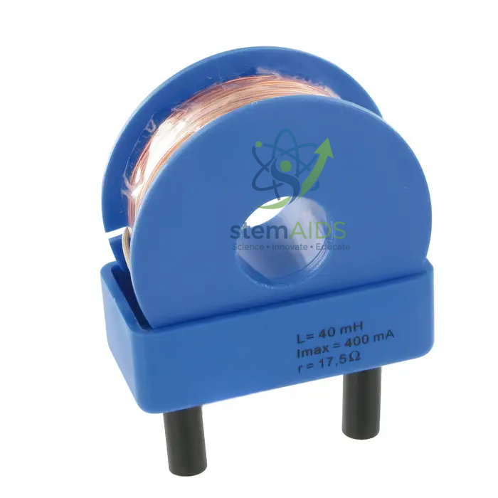
Quick Answer: The UME 70 mH coil is an inductor of 70 millihenries in a blue plug-in housing, with a window showing the copper winding and plug pins underneath, as pictured. The UME 70 mH coil is used in AC and transient practicals where its opposition to changing current is measured and calculated.
What 70 mH Means at Different Frequencies
An inductor’s reactance rises in proportion to frequency, X = 2πfL. For 70 mH that gives about 22 Ω at 50 Hz, about 220 Ω at 500 Hz and about 440 Ω at 1 kHz. With a signal generator, an AC ammeter and a voltmeter across the coil, students can check these figures, plot reactance against frequency and find the slope, which is 2πL.
The winding also has ordinary resistance, which a multimeter on its ohms range will show. At low frequency that resistance can be comparable with the reactance, so the measured impedance is √(R² + X²) rather than X alone, and students see why a real coil is not a pure inductor.
Resonance and Time Constants
Combined with a capacitor, the UME 70 mH coil forms a tuned circuit resonating at f = 1/(2π√(LC)). With a 1 µF capacitor that is about 600 Hz; with 10 µF it falls to about 190 Hz. Sweeping a signal generator through those values and watching the current peak is a clear demonstration of resonance.
In a DC circuit with a resistor, current through the coil grows with time constant τ = L/R. With 100 Ω in total that is 0.7 ms, so a square-wave generator and an oscilloscope are the natural tools for seeing the exponential rise and fall.
Practicals With the Coil
- Measuring inductive reactance against frequency and finding L from the gradient
- Locating the resonant frequency of an LC circuit with a signal generator
- Viewing the exponential rise of current in an RL circuit on an oscilloscope
- Building simple low-pass or high-pass filters with a resistor module
Specifications
| Product | UME coil (inductor) module |
| Inductance, from title | 70 mH |
| Housing in photograph | Blue housing with a window onto the winding and plug pins underneath |
| Typical measurements | Reactance, impedance, resonance, RL time constant |
| Format | UME plug-in module |
| Current rating | Confirm at enquiry |
Care & Handling
- Keep currents within the coil’s rating to avoid heating the winding
- Expect a brief induced voltage when a DC current in the coil is switched off, and keep circuits low-voltage
- Do not drop the module; a damaged former can break the fine winding
- Keep the plug pins straight and clean
Why Choose LabEquip
Teachers building AC practicals on the UME board need a coil large enough to give clear reactance at audio frequencies, and 70 mH does that. Pair it with a capacitor module such as the UME 1000 µF capacitor, which gives a slow resonance near 19 Hz; contact LabEquip to add it to your set, or see more physics lab equipment.
Frequently Asked Questions
What is the reactance of a 70 mH coil at 50 Hz?
About 22 Ω, from X = 2πfL. At 1 kHz the reactance rises to about 440 Ω, because reactance is proportional to frequency.
Why does the measured impedance differ from the calculated reactance?
The winding has its own resistance. Impedance combines both as the square root of resistance squared plus reactance squared, so at low frequency the resistance makes a noticeable difference.
What resonant frequency does it give with a 1 µF capacitor?
About 600 Hz, from f = 1/(2π√(LC)). A 10 µF capacitor lowers it to about 190 Hz.
What happens when the DC supply to the coil is disconnected suddenly?
The collapsing magnetic field induces a voltage that tries to keep the current flowing. For an instant it can be much larger than the supply, so circuits stay low-voltage and a diode across the coil is often used to absorb it.
How can I measure the inductance myself?
Measure the current through the coil and the voltage across it at a known AC frequency to get the impedance, allow for the winding resistance, and divide the reactance by 2πf. An LCR meter gives a direct reading.
What current can the coil carry?
The current rating is not stated in the listing and can be confirmed at enquiry; signal-generator practicals normally use only small currents.
Last Updated: October 2026




Reviews
There are no reviews yet.