












In Stock
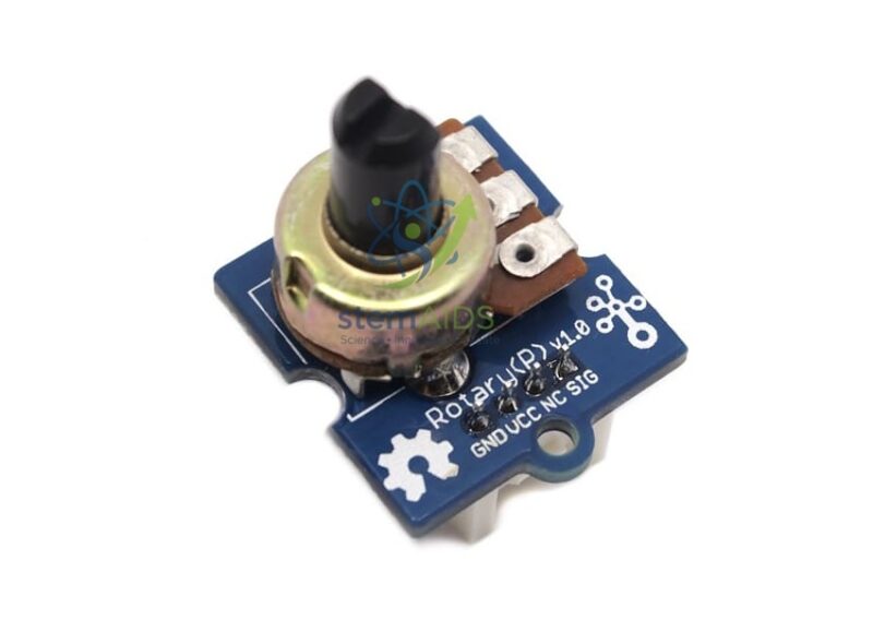
Grove Rotary Potentiometer Module
$2.41
Quick Answer: The Grove Rotary Potentiometer Module is a knob-operated variable resistor mounted on a small board with a Grove connector. Turning the knob changes the voltage on its signal pin, so a microcontroller reads a smoothly varying number that students use to control brightness, speed, servo angle or a threshold.
What Turning the Knob Does Electrically
A rotary potentiometer has a resistive track and a sliding contact, the wiper, that moves as the shaft turns. With the two ends of the track connected to supply and ground, the wiper picks off a fraction of the supply voltage, so the module is really an adjustable voltage divider. Some catalogues call the same Grove part a rotary angle sensor, because the reading tracks how far the shaft has been turned.
On an Arduino-type board the analog input normally reports that voltage as a number from 0 to 1023, and the micro:bit’s analog read uses the same range. Students meet the map function when they rescale that number to something useful, such as 0 to 180 degrees for a servo or 0 to 255 for LED brightness. Few exercises show more clearly that a sensor produces data and the code decides what the data means.
Because a potentiometer is predictable and hard to damage, it is often the first analog input taught, ahead of sensors whose readings drift, such as light or temperature modules. The rotation angle and track resistance are not in the listing title, so confirm them if a project depends on them.
Classroom Uses
- Dimming an LED with pulse-width modulation as the knob turns
- Steering a servo arm to the angle set by the knob
- Setting an alarm threshold for a light or temperature sensor project
- Choosing menu items or game speed in a student-built program
- Plotting the analog value live to show how rotation and reading relate
Specifications
| Item | Rotary potentiometer (knob) on a Grove module board |
| Output | Analog voltage proportional to shaft position |
| Connection | Grove 4-pin connector using one analog signal line |
| Typical reading | 0 to 1023 on 10-bit analog inputs |
| Pairs with | LEDs, servos, buzzers and displays on a Grove shield |
| Rotation angle and resistance value | Confirm at enquiry |
Care & Handling
- Turn the knob gently up to its end stops; forcing it past a stop can break the internal track.
- Use a Grove cable rather than pushing jumper wires into the socket, which can spread the contacts.
- Keep the module away from liquids and from metal offcuts on the bench.
Why Choose LabEquip
Coding teachers tend to order potentiometer modules in class sets, since nearly every beginner Grove project needs a manual input. LabEquip offers it within the STEM kits range, and it pairs naturally with the Grove RGB LED bar for a level-meter exercise. For quantities or mixed module orders, use the contact page.
Frequently Asked Questions
What is the difference between a potentiometer and a rotary encoder?
A potentiometer gives an absolute position: the same knob angle always gives roughly the same reading, and it has end stops. A rotary encoder turns without limit and sends pulses as it moves, so the program counts steps. For simple level control a potentiometer is easier to program.
Why does the reading jitter slightly when I do not touch the knob?
Small changes come from electrical noise and the resolution of the analog converter. Averaging several readings, or ignoring changes of one or two counts, gives a steady value. This is a useful lesson in filtering real sensor data.
Can the potentiometer control a motor directly?
No. The module only produces a small signal voltage. The microcontroller reads it and then drives the motor through a motor driver, or positions a servo with a pulse signal. Connecting a motor straight to the potentiometer would overload it.
Is this the same as the Grove rotary angle sensor?
The two names are used for the same kind of Grove part: a knob-operated potentiometer on a module board. Both give an analog reading that changes with shaft position. Compare the photograph and module documentation if you need to match an existing lesson plan exactly.
How do I scale the value to a servo angle?
Read the analog value, then use a map function to convert the range 0 to 1023 into 0 to 180. Send that result to the servo. Printing both numbers side by side helps students see the conversion working as they turn the knob.
What does the module teach beyond turning a knob?
It introduces analog input, voltage dividers, scaling with the map function and the idea of feedback when students watch an output respond. These ideas carry straight over to light, sound and temperature sensors later in a course.
Last Updated: September 2026
You must be logged in to post a review.
Bestsellers

Sale

Sale

Sale

Sale


Reviews
There are no reviews yet.