


Sale
In Stock
Resistance Measurement Board
Original price was: $12.41.$6.09Current price is: $6.09.
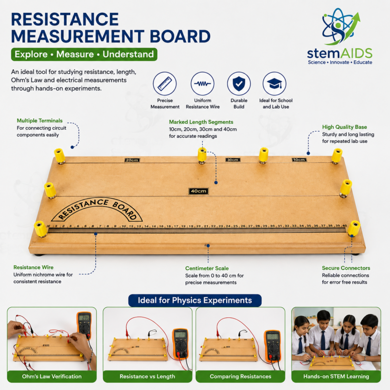
Quick Answer: The Resistance Measurement Board is a bench apparatus for measuring how the resistance of a wire depends on its length. The listing image shows a resistance wire stretched along a centimetre scale on a wooden base, with terminals at intervals so that different lengths can be connected to a meter or into a circuit.
Measuring Resistance Length by Length
The resistance of a uniform wire is proportional to its length and inversely proportional to its cross-sectional area, as described by R = ρL/A. The resistance measurement board isolates the length part of that relationship. Connecting between terminals that are farther apart places a longer piece of the same wire in the circuit, so students can record resistance at several lengths and plot a straight-line graph through the origin.
Resistance can be read directly with a multimeter set to its ohms range, or found by the voltmeter-ammeter method: pass a small current through the chosen length, measure the potential difference across it and divide. The second method doubles as an Ohm’s law investigation, since changing the supply and recording several pairs of voltage and current shows whether the wire’s resistance stays constant.
With the wire’s diameter measured by a micrometer screw gauge, the gradient of the resistance-length graph gives the resistivity of the alloy. Resistance wire is typically an alloy such as constantan or nichrome, chosen because its resistance is high and changes relatively little as it warms. The alloy and gauge used on this board should be confirmed when ordering.
Specifications
| Apparatus type | Resistance versus length board |
| Conductor | Resistance wire along a centimetre scale |
| Connections | Terminals at intervals along the wire, as pictured |
| Base | Flat wooden board |
| Used with | Multimeter, or ammeter, voltmeter and low-voltage supply |
| Wire alloy and gauge | Confirm at enquiry |
Applications
- Showing that resistance is proportional to length for a uniform wire
- Verifying Ohm’s law with voltmeter and ammeter readings
- Determining resistivity from the wire diameter and the graph gradient
- Practising correct meter placement and circuit drawing
- Discussing measurement uncertainty and repeat readings
Care & Handling
- Keep currents small and switch off between readings; a warming wire changes its resistance.
- Tighten terminal screws firmly on clean leads, because loose contacts add resistance of their own.
- Do not bend, kink or pull the wire, which alters its cross-section and spoils the uniformity.
- Store the board flat and dry so the scale stays legible and the wooden base does not warp.
Why Choose LabEquip
Physics teachers choose this board for the electricity practicals on resistance and resistivity, which appear at both secondary and college level. LabEquip offers it in the STEM kits range, alongside the Series Resistor Network Apparatus for the next step of combining resistors. Place orders through the contact page.
Frequently Asked Questions
Why does a longer wire have more resistance?
In a longer wire the charge carriers have to travel through more of the metal, colliding with more ions on the way. Each extra length adds the same amount of resistance, so for a uniform wire resistance increases in direct proportion to length.
Should I use a multimeter or an ammeter and voltmeter?
A multimeter on the ohms range gives a quick direct reading. The ammeter-voltmeter method takes longer but shows how resistance is defined, voltage divided by current, and lets students test Ohm’s law at the same time. Many teachers use both and compare.
Where do the ammeter and voltmeter go in the circuit?
The ammeter goes in series so the whole current passes through it. The voltmeter connects in parallel across only the length of wire being measured, from one chosen terminal to the other.
How is resistivity calculated from the results?
Plot resistance against length; the gradient is the resistance per metre. Multiply the gradient by the cross-sectional area of the wire, found from its diameter with a micrometer, to get the resistivity in ohm metres.
Why does the resistance reading change if the current is left on?
The current heats the wire, and the resistance of most metals rises with temperature. Keeping the current small, switching off between readings and taking measurements quickly keep the wire close to room temperature.
Why does the graph not pass exactly through zero?
The leads, crocodile clips and terminal contacts add a small resistance of their own, which appears as a constant offset in every reading. The gradient is unaffected, so the resistivity calculation remains valid even with the offset.
Last Updated: September 2026
You must be logged in to post a review.
Bestsellers



Sale

Sale

Sale


Reviews
There are no reviews yet.