
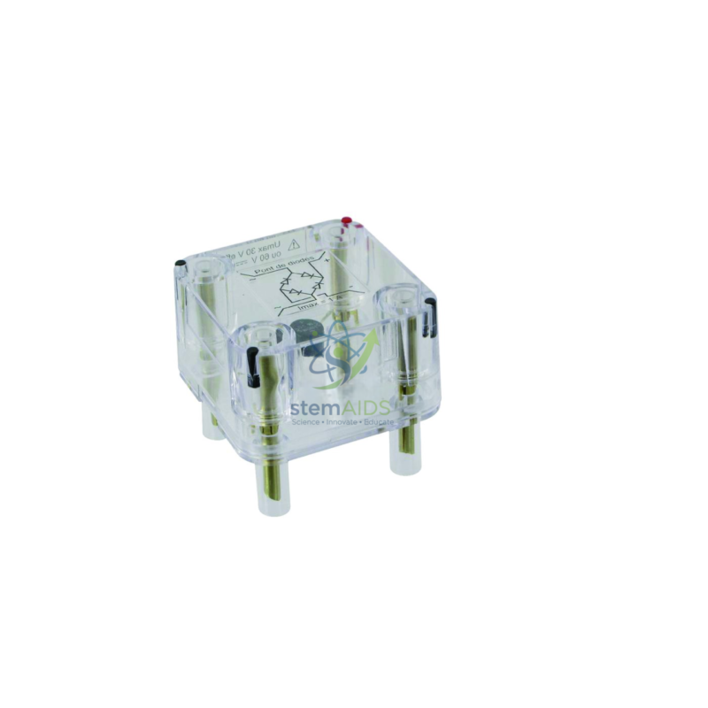
Quick Answer: The UME diode bridge is a plug-in circuit module holding four diodes in the bridge arrangement inside a clear housing, with plug pins underneath for the UME module board, as pictured. Fed with low-voltage AC, the UME diode bridge delivers full-wave rectified DC, and the transparent case lets students see the four diodes they are reasoning about.
Following the Current Through the Bridge
In a diode bridge the four diodes are arranged so that on each half-cycle of the AC input two of them conduct and two block. On one half-cycle, current enters at one AC terminal, passes forward through a diode to the load, returns through a second diode and leaves by the other AC terminal. On the next half-cycle the other pair takes over, and the current through the load still flows the same way.
Students can trace this path with a finger on the clear housing, then confirm it on an oscilloscope: the output shows both halves of the sine wave on the same side of the axis, with twice as many peaks per second as the input. Each peak is slightly lower than the input peak because the current always crosses two diode junctions in series.
Specifications
| Product | UME diode bridge module |
| Circuit | Four diodes in a bridge arrangement |
| Housing in photograph | Clear plastic block with plug pins underneath |
| Function | Full-wave rectification of low-voltage AC |
| Format | UME plug-in module for the matching connection board |
| Maximum current and voltage | Confirm at enquiry |
Adding Smoothing in the Module Format
Plugging a large capacitor such as the UME 1000 µF capacitor across the output of the UME diode bridge turns the humped waveform into a nearly steady voltage with a small ripple. Adding a load resistor and watching the ripple grow as the resistance is reduced shows why power supplies need larger capacitors for larger currents.
Because each part is a separate module on the board, the circuit can be built in stages: the low-voltage AC supply alone, then the bridge, then the capacitor, then the load, with a scope trace recorded at each step. That staged build is what makes rectification understood rather than memorised.
Practicals
- Displaying full-wave rectified waveforms on an oscilloscope
- Building a smoothed DC supply step by step with a capacitor and a load
- Measuring the voltage lost across the two conducting diodes
- Investigating how ripple changes with load current
Care & Handling
- Feed the module only from a low-voltage laboratory AC supply, never from the mains
- Keep currents within the ratings the module is supplied for
- Store modules in a tray so the plug pins stay straight
- Wipe the clear housing with a soft dry cloth; solvents can cloud it
Why Choose LabEquip
Schools that teach electronics with the UME module system add the diode bridge so rectification sits on the same board as every other circuit. LabEquip supplies it with the matching capacitor module; contact LabEquip to extend your set, or browse our physics lab equipment.
Frequently Asked Questions
Why is the diode bridge housed in a clear case?
So the four diodes and their connections stay visible. Students can match what they see to the circuit symbol and work out which pair conducts on each half-cycle.
What does the oscilloscope show at the bridge output?
Both halves of the AC wave appear on the same side of the axis as a series of humps at twice the supply frequency. A 50 Hz supply gives 100 peaks per second at the output.
Why is the output peak a little lower than the input?
Current passes through two conducting diodes in series, and each drops a small voltage, typically around 0.6 to 0.7 V for silicon diodes. The output peak is lower by the sum of the two drops.
How do I smooth the output?
Connect a capacitor across the output, observing its polarity if it is electrolytic. It charges at each peak and supplies the load between peaks, leaving a small ripple.
Can the bridge be fed from the mains?
No. The module is for low-voltage AC from a laboratory supply or transformer. Mains voltage must never be connected to student circuit modules.
What is the module’s current rating?
The listing names the module but not its ratings, which can be confirmed at enquiry. Keep currents small, as in normal student circuits, until the rating is known.
Last Updated: October 2026




Reviews
There are no reviews yet.