
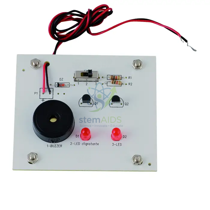
Quick Answer: The Sound and Light Module is a small circuit board carrying a buzzer, LEDs and a selector switch, with a supply lead, that turns an electrical signal into sound, light or both. Students use the sound and light module as the output stage of alarm, signalling and control projects and to discuss how electrical energy becomes sound and light.
From Electrical Signal to Sound and Light
A buzzer converts electrical energy into sound. In the common piezoelectric type, a thin disc of special ceramic flexes when a voltage is applied, and an oscillating circuit makes it flex back and forth rapidly, producing a tone. An LED converts electrical energy into light inside a semiconductor junction, and it needs a series resistor to keep the current safely low.
The board in the product photograph is a white panel with a round black buzzer, two red LEDs, a slide switch, small transistors and resistors, mounting pillars at the corners and a red and black supply lead. The transistors let a small control signal switch the larger current the buzzer and LEDs need.
Using the Board as an Output Stage
Electronic systems are often described as input, process and output. The sound and light module covers the output part: once a sensor and a processing circuit have decided that something should happen, for example that light has fallen below a threshold or a door has opened, this board makes the result noticeable to people.
That makes it a natural final block in project work, and a clear example for discussing energy transfers, since one board shows electrical energy becoming both sound and light.
Applications
- Completing an alarm circuit as the output stage after a sensor and processing board
- Demonstrating energy transfer from electrical to sound and light
- Signalling projects such as door alarms, timers or reaction games
- Teaching the role of a transistor as a switch driving an output
Specifications
| Product | Sound and light output module |
| Outputs | Buzzer and two LEDs, as photographed |
| Controls | Slide switch on the board |
| Driver components | Transistors and resistors on the board |
| Supply required and switch functions | Confirm at enquiry |
Care & Handling
- Connect the supply lead with the correct polarity, red to positive
- Use only the supply specified for the board
- Hold the board by its edges or pillars and avoid touching the components while powered
- Store in a box so components are not bent or knocked off
Why Choose LabEquip
Design and technology departments and physics teachers buy output modules like this so students can finish a working system without soldering. LabEquip supplies it with the conversion and processing model among its physics equipment; supply and switch details can be confirmed through the contact page.
Frequently Asked Questions
Why do the LEDs need resistors?
An LED passes very little current below a certain voltage and then a rapidly rising current above it. A series resistor limits the current to a safe value so the LED is not damaged.
What does the transistor on the board do?
It acts as an electronic switch. A small current into the transistor controls a much larger current through the buzzer or LEDs, so a weak signal from another circuit can operate the outputs.
How does a buzzer turn electricity into sound?
In a piezoelectric buzzer a ceramic disc bends slightly when a voltage is applied. Switching the voltage on and off rapidly makes the disc vibrate, and the vibration produces a sound wave.
Why does an LED only light one way round?
An LED is a diode, so it conducts in one direction only. Connected the other way round it blocks the current and stays dark.
What projects can the module be used in?
Door and light alarms, timers, reaction games, warning signals and any system where a result needs to be seen or heard. It is usually connected after a sensor and a control board.
Can the supply be connected the wrong way round?
Avoid it. LEDs will simply not light, but the driver circuit and buzzer may not tolerate reversed polarity. Always connect red to positive and black to negative.
Last Updated: October 2026






Reviews
There are no reviews yet.