
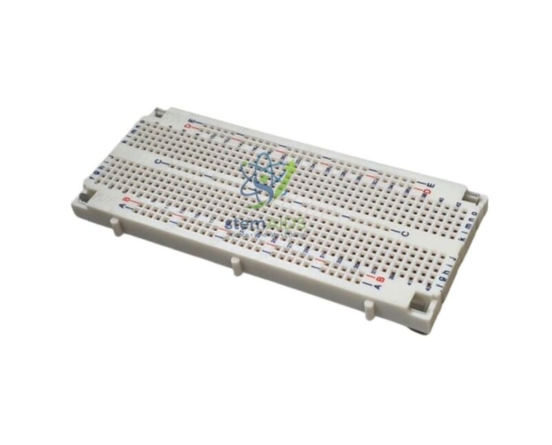
Quick Answer: The Silk Screened 555 Contact Connection Board is a solderless breadboard with the 555 contacts given in its name and printed (silk-screened) markings, shown in the photograph as a white board with rows of holes and edge rails. On a 555-contact connection board, component leads and wires push into spring contacts, so circuits are built, tested and changed without soldering.
How the Contacts Are Linked
Under the holes of the 555-contact connection board, strips of spring metal join them in groups. On most breadboards the holes in each short row on either side of the central channel are connected together, while the long lines along the edges serve as supply rails. A dual in-line chip straddles the channel so each of its pins lands in a separate group. Some boards split their rails halfway along, so a quick meter check before relying on a rail saves confusion later.
The printed markings are what make the board easy to teach with. Where holes carry row and column labels, a circuit can be given as grid references, so every student builds the same layout and a teacher can check a circuit by reading coordinates instead of tracing wires.
Specifications
| Product | Solderless connection board (breadboard) |
| Contacts, from title | 555 |
| Markings | Silk-screened (printed) labels |
| Shown in photograph | White board with rows of contact holes and edge rails |
| Suitable for | Low-voltage electronic circuits and dual in-line chips |
| Contact spacing and largest lead size | Confirm at enquiry |
Good Breadboard Practice
On a breadboard, use solid-core jumper wire cut short and laid flat, and keep component leads straight so they enter the contacts cleanly; thick leads and stranded wire spread the springs and leave loose contacts later. Build in stages, test each stage, and keep the power off while moving parts.
Breadboards suit low-voltage, low-current circuits: LED circuits, transistor switches, logic gates, op-amp stages and timers. The 555 in this board’s name counts its contacts; the board holds a 555 timer chip as readily as any other dual in-line chip.
Circuits to Build
- Building LED, transistor and logic gate circuits in electronics lessons
- Prototyping a timer or op-amp circuit before soldering it
- Following circuit layouts given as grid references on worksheets
- Testing sensor circuits such as LDR and thermistor potential dividers
Care & Handling
- Use solid-core wire and component leads that suit the contacts, and never force thick leads
- Keep supply voltages low and switch off before changing the circuit
- Clear out trimmed leads and wire scraps that could short adjacent rows
- Store the board flat and covered to keep dust out of the contacts
Why Choose LabEquip
Electronics and physics teachers buy breadboards in class sets, because every student or pair needs one for circuit practicals. Use them with test hook clips for hands-free measurements, browse the rest of our physics lab equipment, and contact LabEquip for class quantities.
Frequently Asked Questions
Is the 555 in the name the timer chip?
No. It is the number of contacts given in the board’s name. The board holds a 555 timer chip as easily as any other dual in-line chip.
Which holes are connected together?
Holes are linked in groups by spring strips underneath, usually short rows either side of the central channel and long rails along the edges. Follow the printed markings and check with a meter if unsure.
Why does a chip go across the central channel?
So each pin lands in its own group of contacts. If the chip sat on one side, pins opposite each other would be connected together.
Why has my circuit stopped working after moving a wire?
Loose contacts are the usual cause: a lead not fully inserted, a spring spread by a thick wire, or a wire in the wrong row. Check each connection against the layout.
What does silk-screened mean?
The markings are printed onto the board surface. Labels help students find the right hole and let worksheets give layouts as grid references.
Can mains-powered circuits be built on a breadboard?
No. Breadboards are for low-voltage, low-current circuits. Their exposed contacts and close spacing make them unsuitable for mains voltage.
Last Updated: October 2026




Reviews
There are no reviews yet.