
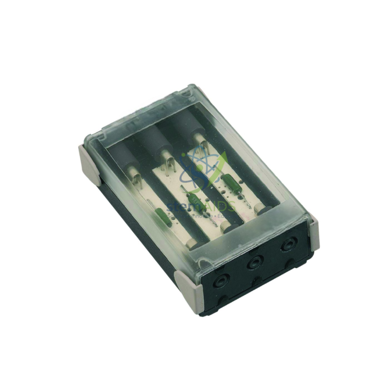
Quick Answer: This unknown resistor set is a module with a clear cover holding three resistors, each connected to its own pair of sockets, as pictured, so that students can find their resistances by experiment. It turns resistance measurement into a practical task: determine the values, then check them by a second method.
Three Ways to Find a Resistance
The quickest method is a digital multimeter on its resistance range, connected across one pair of sockets with the resistor out of any powered circuit. The meter passes a small known current and displays the result directly.
The voltmeter-ammeter method uses Ohm’s law. Connect the resistor in series with a supply, a rheostat and an ammeter, with a voltmeter across the resistor alone, and take several readings; the gradient of the voltage against current graph is the resistance. Students should notice that the ammeter then also carries the voltmeter’s current, an error that is negligible for small resistances but grows for large ones, when connecting the voltmeter across both resistor and ammeter becomes the better choice.
A Wheatstone or metre bridge compares the unknown with a known resistance by finding a balance point where a galvanometer reads zero. Because no current flows through the galvanometer at balance, the result does not depend on meter calibration, which makes it the most precise school method.
Series and Parallel Checks
Once the three values are known, the module becomes a test of the combination rules. Link two resistors in series and measure: the total should equal the sum. Link them in parallel and the total should satisfy 1/R = 1/R₁ + 1/R₂, always smaller than the smaller resistor. Agreement between measured and calculated values, within the uncertainty of the meters, is a satisfying end to a practical sequence.
Practical Uses
- Measuring resistance with an ohmmeter, the voltmeter-ammeter method and a metre bridge
- Comparing the precision of different measurement methods
- Testing series and parallel resistance formulas with measured values
- Assessment practicals in which students determine unknown values
Specifications
| Contents | Three resistors in one module, as pictured |
| Connections | A separate pair of sockets for each resistor |
| Housing | Module with clear cover |
| Purpose | Resistance measurement and combination practicals |
| Resistor values, tolerance and power rating | Confirm at enquiry |
Care & Handling
- Keep the current low during voltmeter-ammeter measurements so the resistors do not heat up and change value.
- Never connect an ohmmeter across a resistor that is part of a powered circuit.
- Keep the sockets clean so contact resistance does not add to small readings.
- Store the module with other circuit modules in a dry tray.
Why Choose LabEquip
Teachers buy sets of mounted resistors for practical assessments, where students must find values themselves instead of reading them off a label. Pair the module with a meter bridge and a digital multimeter, both in the LabEquip Physics Equipments category.
Frequently Asked Questions
Which method gives the most accurate resistance?
A balanced Wheatstone or metre bridge is usually the most precise school method, because it compares the unknown with a known resistance at zero galvanometer current. A good digital multimeter is quicker and accurate enough for most purposes.
Why do my voltmeter-ammeter and multimeter results differ slightly?
Each method has its own errors: meter calibration, the current drawn by the voltmeter, contact resistance and heating of the resistor. Small differences are normal, and explaining them is part of the practical.
How should the voltmeter be connected?
For low resistances, connect the voltmeter directly across the resistor so the ammeter’s resistance is excluded. For high resistances, connect it across both resistor and ammeter so the voltmeter’s current is not added to the ammeter reading.
Can the three resistors be combined?
Yes. Leads between the socket pairs connect them in series or parallel, so students can compare measured combined values with values calculated from the individual resistances.
Why must an ohmmeter not be used on a powered circuit?
The ohmmeter works by passing its own small current. An external supply adds an unknown current, giving a false reading and possibly damaging the meter.
Are the resistor values marked?
The point of the module is that students determine the values by measurement, and teachers can record reference values with a multimeter for checking results. The nominal values for this set can be confirmed when you enquire.
Last Updated: October 2026




Reviews
There are no reviews yet.