
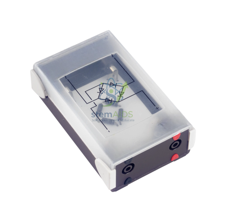
Quick Answer: The Diode Bridge is a set of four semiconductor diodes connected in a closed loop so that an alternating input produces an output current that always flows the same way. A diode bridge rectifier is used in physics and electronics labs to demonstrate full-wave rectification, the first stage of almost every mains-powered DC supply.
Two Diodes at a Time
The four diodes are arranged so that, whichever input terminal is positive at a given moment, there is one path through the bridge to the positive output and one path back from the negative output. During one half-cycle of the alternating input a diagonal pair of diodes conducts; during the next half-cycle the other pair takes over. The load therefore receives current in the same direction on both halves of the wave.
Because two diodes are always in the current path, the output peak is lower than the input peak by two diode voltage drops, which is easy to see on a low-voltage teaching supply. The output is not yet steady direct current but a train of humps, all on the same side of zero, at twice the supply frequency. Smoothing with a capacitor is the next stage, and the diode bridge and capacitor module is set up to show it.
Specifications
| Component | Bridge rectifier (four diodes) |
| Terminals | Two AC inputs; positive and negative DC outputs |
| Function | Full-wave rectification |
| Output before smoothing | Pulsating DC at twice the supply frequency |
| Voltage and current rating | Confirm at enquiry |
Seeing Rectification on an Oscilloscope
Connect a low-voltage AC supply to the two input terminals and a resistor across the output terminals as the load. An oscilloscope then shows the rectified output, and with care the input as well. Students can compare it with half-wave rectification from a single rectifier diode and see how the bridge fills in the missing half-cycles, doubling the ripple frequency and making smoothing easier. Watch the oscilloscope earths: the input and output of a bridge do not share a common reference, so on a mains-powered oscilloscope the two probe earth clips must not go to different points of the circuit.
Applications
- Full-wave rectification practicals at school and college level
- Comparing half-wave and full-wave outputs on an oscilloscope
- Building a simple DC supply from a transformer, bridge and smoothing capacitor
- Making a DC device work whichever way round its supply is connected
Care & Handling
- Identify the AC and the plus and minus terminals before wiring the diode bridge; swapping the output leads reverses the polarity at the load.
- In student work, feed the bridge from a low-voltage AC source such as a laboratory transformer, never directly from the mains.
- Stay within the bridge’s voltage and current rating; a bridge carrying a large current needs a heat sink.
- Let the bridge cool before touching it after a long run at high current.
Why Choose LabEquip
Electronics and physics labs order diode bridges for power-supply practicals, usually with transformers, resistors and capacitors to match. LabEquip supplies them within our physics lab equipment range; send us the voltage and current you need through the contact page.
Frequently Asked Questions
Why does a bridge rectifier need four diodes when half-wave needs only one?
A single diode simply blocks one half of every cycle. The bridge uses four so that the negative half-cycles are steered through a second path and come out the same way round as the positive ones. Nothing is discarded, so the average output is about twice that of half-wave rectification.
What frequency is the ripple from a diode bridge?
Twice the supply frequency, because there is one hump of output for every half-cycle. From a 50 Hz supply the ripple is at 100 Hz, which is easier to smooth than the 50 Hz ripple left by a half-wave rectifier.
Why is the output peak lower than the input peak?
In every half-cycle the current passes through two diodes in series, and each takes a small forward voltage. On a low-voltage teaching supply the difference is easy to measure, and it is one reason some supplies use a centre-tapped transformer with only two diodes.
Can a diode bridge protect a DC device against reversed connections?
Yes. Placed between a DC source and a device, a bridge delivers the correct polarity to the device whichever way round the source is connected, at the cost of two diode drops. It is a common technique in battery-powered equipment.
How do I identify the terminals?
Bridges are normally marked with a wave or AC symbol on the two input terminals and with plus and minus signs on the outputs. If the marks have worn off, a multimeter on its diode-test setting will find the direction of each diode.
Why did my oscilloscope trace short out part of the circuit?
On most mains-powered oscilloscopes every probe earth is joined to the same point. If the two earth clips are attached to different points of a bridge circuit, they short-circuit it through the oscilloscope. Use one earth clip only, or an isolated or differential measurement, when viewing input and output together.
Last Updated: October 2026






Reviews
There are no reviews yet.