
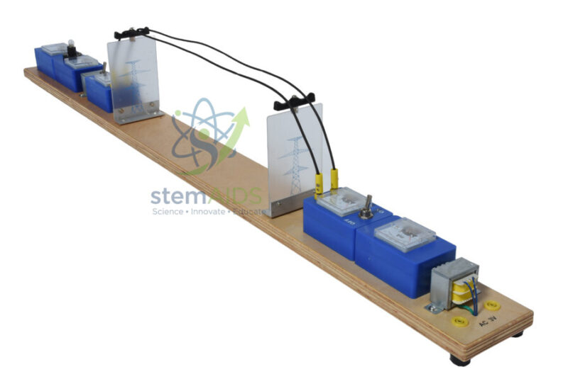
Quick Answer: The Study Model of Electricity Distribution is a long baseboard carrying a scale line on two pylons between a supply end and a consumer end, with modules such as a transformer and switch units at the ends. This electricity distribution model lets a class build and measure a miniature grid and see why electricity travels over distance at high voltage.
The Path From Power Station to Consumer
Electricity reaches homes in stages. A power station generates it, a step-up transformer raises the voltage, long transmission lines carry it across country, and step-down transformers near the consumer lower the voltage again for distribution. The electricity distribution model lays those stages along one board, so students can follow the path from left to right.
In the product photograph the board carries two clear pylons supporting a pair of wires, blue modules at both ends and a transformer at the far end. Because the line is deliberately given noticeable resistance, the losses that are hard to sense on a real grid become large enough to measure.
Measuring What the Line Costs
With a lamp as the consumer and no transformers in use, students measure the voltage at both ends of the line and find a clear drop; the lamp at the far end glows dimmer than it would at the source. The drop equals the line current times the line resistance, and the power lost is that drop times the current.
Adding transformers changes the picture. Stepping the voltage up before the line reduces the current for the same power, and stepping it down afterwards restores a usable voltage. The far-end lamp brightens, and the measured line loss falls, which is the whole argument for high-voltage transmission demonstrated on one bench.
What Students Investigate
- Measuring the voltage drop along the line with and without transformers
- Calculating the power lost in the line from current and voltage drop
- Comparing lamp brightness at the consumer end in each arrangement
- Explaining the stages of the National Grid or any national transmission network
Specifications
| Product | Study model of electricity distribution |
| Layout | Long baseboard with a line on two pylons |
| Modules in photograph | Switch and meter-style units, transformer |
| Topic | Transmission losses and the role of transformers |
| Supply required and full module list | Confirm at enquiry |
Care & Handling
- Run the model only from the low-voltage teaching supply specified for it
- Make all connections with the supply off and let the teacher check them before switching on
- Do not touch transformer cores or line wires while the model is running
- Lift the board from both ends; it is long and can bend if carried from the middle
Why Choose LabEquip
Secondary schools use this kind of model because power transmission is examined heavily and is difficult to show without one. LabEquip supplies it with the component-level electricity transmission model among its physics equipment; supply and module questions can be sent through the contact page.
Frequently Asked Questions
Why does the far-end lamp glow dimmer without transformers?
Current flowing along the line causes a voltage drop across the line’s resistance. Less voltage is left for the lamp at the consumer end, so it receives less power and glows dimmer.
What do the transformers do in the model?
The step-up transformer raises the voltage and lowers the current sent along the line, and the step-down transformer lowers the voltage again for the consumer. With less current in the line, much less energy is lost as heat.
Why do real grids use alternating current?
Transformers only work with a changing current, because they rely on a changing magnetic flux. Alternating current lets voltages be changed easily, although some very long links now use high-voltage DC with electronic converters.
What supply does the model need?
It should be run from the low-voltage teaching supply specified for the model and never directly from the mains. The teacher should check all connections before switching on.
How can students calculate the power lost in the line?
Measure the current in the line and the voltage at each end. Multiply the difference in voltage by the current to get the power lost as heat in the line.
Is the line on the model a fair scale of a real line?
Not in resistance. The model line is given relatively high resistance so the losses are measurable over a short board, whereas real lines have low resistance per kilometre but run for hundreds of kilometres.
Last Updated: October 2026




Reviews
There are no reviews yet.