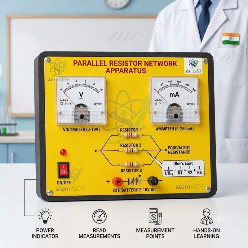
Quick Answer: The Parallel Resistor Network Apparatus is a physics teaching aid with resistors connected side by side between two common points, used to measure branch currents and to show that the equivalent resistance of a parallel network is smaller than any single resistor in it.
Measuring a Parallel Network
In a parallel network every resistor is connected across the same two points, so each branch has the same potential difference. The current divides: more flows through the smaller resistance and less through the larger, and the branch currents add up to the total current drawn from the supply. By moving an ammeter from branch to branch and placing a voltmeter across the network, students confirm both statements from their own readings.
The result that surprises most classes is that adding another resistor in parallel lowers the total resistance. The reciprocal rule, 1/R = 1/R1 + 1/R2 + and so on, explains it: each extra branch is another path for current. Students check it by measuring the total current and voltage, calculating R = V/I and comparing the answer with the calculated value. Two equal resistors in parallel give half the value of either one.
Apparatus of this type usually mounts the resistors on a base with terminals or sockets so that branches can be added or removed; the resistor values, number of branches and connection type of this unit should be confirmed. Used with its companion, the Series Resistor Network Apparatus, it lets a class compare both arrangements in one lesson.
Practical Work
- Verifying that branch currents add up to the total current
- Showing that every branch has the same potential difference
- Calculating equivalent resistance and comparing it with R = V/I
- Explaining why household circuits are wired in parallel
Specifications
| Item | Parallel resistor network teaching apparatus |
| Arrangement | Resistors connected in parallel between two common points |
| Rule shown | 1/R = 1/R1 + 1/R2 + … for the equivalent resistance |
| Measurements | Branch currents, total current and common potential difference |
| Used with | Low-voltage DC supply, ammeter, voltmeter and leads |
| Resistor values and connection type | Confirm at enquiry |
Care & Handling
- Use a low-voltage DC supply and switch off between readings so the resistors do not heat up.
- Connect an ammeter in series with a branch, never directly across the supply.
- Make sure terminals are tight, because a loose lead changes the readings.
- Store the apparatus flat in a dry cupboard.
Why Choose LabEquip
Physics teachers choose ready-made apparatus because it removes the loose-wiring errors that spoil many parallel-circuit practicals. LabEquip lists it in the STEM kits range, with meters and related items in the electrical and electronics section. Send your requirements through the contact page.
Frequently Asked Questions
Why is the total resistance lower when resistors are in parallel?
Each resistor adds another path for current, so more current flows for the same voltage. More current at the same voltage means a lower resistance, which the reciprocal rule describes.
How do I calculate the equivalent resistance of a parallel network?
Add the reciprocals of the individual resistances and take the reciprocal of the sum. For two resistors this simplifies to their product divided by their sum.
Where should the ammeter go in a parallel circuit?
In series with the branch you want to measure, or in the main lead for the total current. Never connect an ammeter directly across the supply or across a resistor.
Is the voltage the same across every branch?
Yes. All branches connect to the same two points, so each has the same potential difference, and a voltmeter across any branch gives the same reading.
Why do my branch currents not add up exactly to the total?
Small differences come from meter accuracy, contact resistance at terminals and resistors warming up. Tighten the connections, take readings quickly and keep the meter on the same range.
How are parallel circuits used in real life?
Household sockets and lights are wired in parallel, so each receives the full supply voltage and can be switched on or off without affecting the others.
Last Updated: September 2026